Six-axis IMU — sensor-side hero
Robotics sensing
CAN six-axis IMU module
Development-stage CAN board for raw acceleration and angular velocity with the ST LSM6DS3TR-C. Engineering firmware and host integration are reported locally tested; physical hardware qualification remains pending.
$139 USD per board assembly. Shipping charged separately.
You’ll send your contact details with your cart. Product details and pricing are confirmed by our team.
Product details
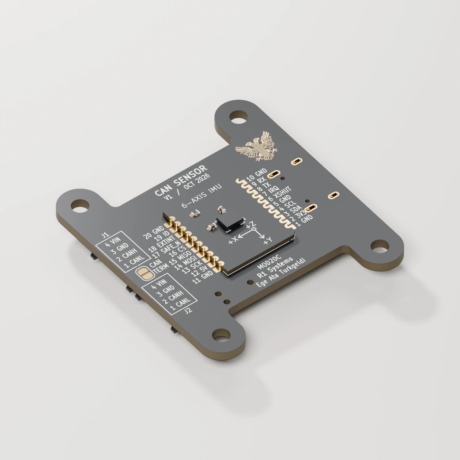
A compact STM32 carrier with one soldered six-axis IMU daughterboard provides raw acceleration and angular velocity with the ST LSM6DS3TR-C. This is a fixed, installed board assembly; the daughterboard is not a user-swappable accessory. The common carrier provides USB-C development access, two connectors on one shared CAN/power bus, selectable termination, and a 20-contact soldered module interface. Daughterboard components face outward on the underside. The gallery shows Blender renders of the October 13 detailed STEP assemblies, with three views of this installed daughterboard. The supplied silkscreen labels and exposed copper artwork are retained, with black soldermask, gold pads and reflective metal surfaces. Internal copper remains behind the opaque board surfaces. Cable mates and wires are omitted. Some components retain simplified envelopes; render materials and highlights are visualization choices. These are CAD renders, not product photographs or qualified clearance drawings. The supplied R1 Family 0.2.0-engineering follow-up reports firmware and host integration implemented and locally tested for this variant. Its family-wide validation report records 77 passing software tests using native mocks and simulated Cyphal nodes; this is not a per-board hardware test count. Physical board testing and ROS 2 runtime validation remain pending. The engineering software includes R1 Sensor Studio for raw six-axis motion views and CAN network diagnostics. Confirm software delivery, licensing, support and integration requirements with your inquiry.
$139 USD per board assembly. Shipping charged separately. Hardware designs and an engineering software baseline are available for integration review. Physical hardware qualification and ROS 2 runtime validation remain pending. Package contents, software delivery, licensing, support and lead time are confirmed by inquiry.
| Price | $139 USD per board assembly. Shipping charged separately. |
|---|
| Assembly | One compact carrier with one soldered daughterboard; 20-contact interface carrying power, I²C, SPI and control signals |
|---|---|
| Processor | STM32G0B1KCU7, Cortex-M0+, 64 MHz; 256 KB flash and 144 KB SRAM |
| PCB outline | 36 × 40 mm including mounting ears; 36 × 26 mm main body. Connectors, components, and cables require additional clearance. |
| Power design target | 9–60 V regulated DC; unqualified. Rail, thermal, startup and transient validation remain open; not a motor-bus surge rating. |
| Bus connectors | Two Molex Pico-EZmateHC 4-pin connectors on one shared CAN/power bus, not independent CAN channels |
| Bus pinout | 1 CAN_L · 2 CAN_H · 3 GND · 4 VIN_BUS |
| Termination | Selectable 120 Ω end-of-bus termination via CAN TERM jumper |
| Development access | USB-C, BOOT and RESET. Follow-up reports a separate Classical CAN SLCAN adapter firmware image for a spare carrier, with daughterboard rails off; physical USB/CAN operation untested. |
| Qualification | Designed hardware; assembled units and system performance are not yet qualified. CAD images use some simplified component envelopes. |
| Sensor | ST LSM6DS3TR-C: three-axis acceleration and three-axis angular velocity |
|---|---|
| Component scales | Acceleration: ±2 / ±4 / ±8 / ±16 g. Gyroscope: ±125 / ±250 / ±500 / ±1000 / ±2000 °/s. |
| Integration | Raw six-axis sensing; no magnetometer or qualified absolute orientation solution. Verify underside mounting transform, bias and timing. |
| Software status | R1 Family 0.2.0-engineering reports firmware and host integration implemented and locally tested with mocks/simulation. Physical hardware qualification and ROS 2 runtime validation pending. |
| Release and test evidence | Supplied family-wide 0.2.0-engineering report lists five compiled STM32 targets and 77 passing software tests. Driver interfaces use mocks; Sensor Studio uses simulated Cyphal nodes. This is reported evidence, not independent hardware verification. |
|---|---|
| Release limits | Physical MCU/USB/CAN, sensing and power qualification pending; ROS 2 runtime untested. Development USB IDs and unsigned engineering binaries are not a production release. Public licensing and support remain to be confirmed. |
| Variant interfaces | Acceleration and angular velocity; orientation unavailable. ROS 2 runtime validation remains pending. |