Sensing · In development · R1 Systems
Modular CAN Sensor Nodes for Robotics
A robot may need distance and motion measurements from several locations, or a radio connection for packet communication. Connecting those devices involves more than choosing a board: the system also needs wiring, power, communications, and software that can interpret their measurements.
R1 Systems is developing CAN-connected sensor nodes around a common carrier design. Each complete sensor or radio listing combines a carrier board with one soldered, variant-specific daughterboard.
All five options are in development and open for integration inquiries. Configuration, validation status, software, pricing, and timing require review; the listings do not establish production-ready hardware or released firmware.
Why use CAN-connected sensor nodes?
A distributed sensor architecture places sensing hardware where the measurement is needed and connects those nodes to the robot’s control system.
CAN provides a shared communication bus, allowing multiple compatible nodes to exchange messages over a common network. Its differential signaling uses the voltage difference between two signal lines to represent data. TI’s CAN signaling overview
For robotics, this approach can offer several practical benefits:
- More flexible sensor placement: locate a node near the part of the robot or environment it needs to observe.
- A common communication backbone: organize compatible devices around one bus rather than separate direct connections to the main controller.
- Clearer subsystem boundaries: separate sensor-specific processing from higher-level robot decisions.
- A path to expansion: plan additional sensing nodes around the network’s wiring, power, and bandwidth requirements.
These are architectural benefits. Actual reliability, latency, update rates, and compatibility depend on the complete implementation.
One carrier with a selected daughterboard
The R1 concept uses a common carrier architecture with a daughterboard selected for the sensing or radio function.
The four sensor and radio options each supply a complete carrier board fitted with one soldered daughterboard. The fifth option supplies the populated carrier without a daughterboard, with carrier KiCad files delivered privately with the board. In the four fitted options, the daughterboard is part of the configuration; it is not presented as a user-swappable accessory.
This modular design approach provides a way to develop different functions around a shared robot-side interface while keeping the sensing hardware specific to its task.
Compare the five options
Choose by the information your host needs: a grid of distances, one range reading, raw motion measurements or radio packets. Choose the carrier alone for custom integration without a fitted module. The four fitted options have product listings and matching CAD views. The carrier-only listing is in preparation; contact R1 to discuss it.
| Module | Measurement or communication | When to consider it |
|---|---|---|
| 8 × 8 multizone ToF | 64 zones of radial distance and per-zone status | Compare distance across a field of view |
| Single-zone ToF | One distance measurement with a programmable region of interest | Monitor distance along a defined sensing direction |
| Six-axis IMU | Three-axis acceleration and three-axis angular velocity | Provide raw motion measurements for estimation or monitoring |
| LoRa radio | Raw radio packet events and a host send API | Integrate radio packets with a CAN-connected host |
| Carrier board — no module | STM32 controller, power, USB-C and shared CAN interface | Develop a custom module or carrier-based application |
These roles are integration starting points. Sensor range and rate limits do not establish measured R1 system performance, navigation capability or radio range.
8 × 8 multizone ToF
The ST VL53L5CX reports an 8 × 8 grid of radial distances and per-zone status. It supplies 64 ranging zones for the host to interpret.
Consider this option when your task needs a distance pattern across the sensor’s field of view, rather than one range reading. Define the mounting position and the nearby surfaces you need to observe.
Plan for field of view, target conditions, the mounting transform and invalid-range status. The engineering bridge maps range/status data; calibrated point clouds are not included. Physical hardware qualification and ROS 2 runtime validation remain pending.
Single-zone ToF
The ST VL53L1X provides a single-zone time-of-flight measurement with a programmable region of interest. The engineering interface exposes range and measurement metadata.
Consider this option when one distance reading can answer your task, such as checking clearance or monitoring distance to a target. It is a simpler measurement to interpret when you do not need a grid of ranges.
Define mounting direction, target conditions, region of interest, update requirements and invalid-reading handling. Published sensor range and rate limits are component limits, not measured R1 board performance. Physical hardware and ROS 2 runtime validation remain pending.
Six-axis IMU
The ST LSM6DS3TR-C supplies raw acceleration and angular velocity across three axes each. The engineering interface exposes these measurements without an orientation solution.
Consider this option when your host needs motion measurements for application-specific estimation or monitoring. Define how those readings will contribute to your robot’s control or state estimation.
The board has no magnetometer or qualified absolute orientation solution. Verify the underside mounting transform, sensor bias and timing, and plan calibration and estimation in your host software. Physical hardware and ROS 2 runtime validation remain pending.
LoRa radio
The Seeed Wio-SX1262 is the radio option. The engineering software exposes raw packet events and a Python send API, with up to 128 application bytes per packet.
Consider this option when your project needs radio packet communication and you can define the host-side packet handling, payload and timing requirements. CAN remains the robot-side interface.
An appropriate external antenna is required. Review the operating region, antenna and assembled-system RF requirements. The listing does not include a LoRaWAN stack, an automatic CAN-to-radio bridge or a range guarantee. Physical radio and host integration require validation.
Carrier board — no module
This option supplies the populated carrier without a sensor or radio daughterboard. The carrier alone has no distance measurement, motion sensor or LoRa radio function.
Consider it when you want the common carrier platform for custom integration, rather than a fitted sensor or radio node. Carrier-board KiCad design files will be supplied privately with the board.
Adding a daughterboard requires electrical, firmware and mechanical integration through the 20-contact solder interface. The matching current KiCad project is pending delivery; confirm its revision, file set and license before fulfillment. Custom firmware and physical hardware qualification require review.
Shared carrier and installation clearance
All five options share a compact carrier with a 36 × 40 mm carrier outer profile with a 36 × 26 mm main carrier body, based on the source CAD.
Those dimensions provide an initial reference for enclosure planning. They are not a complete installed envelope: connectors, components, mounting, wiring, and sensing clearance must also be considered.
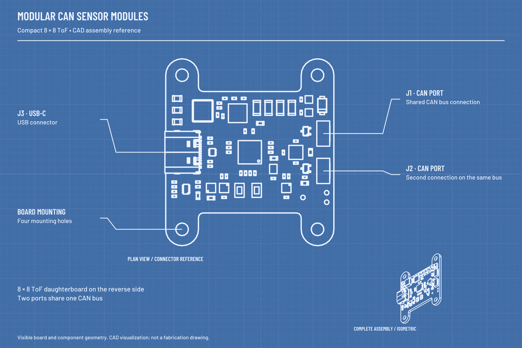
This reference illustration depicts the compact multizone-depth configuration. The current catalog has separate CAD galleries for each fitted option. Carrier-only render images are prepared separately while its listing remains a draft. CAD visualizations do not establish qualified hardware or measured performance.
Two ports on one shared CAN bus
The carrier design provides two ports connected to one shared CAN bus. They should not be interpreted as two independent CAN channels.
This arrangement can support a practical connection layout for a distributed network. The complete installation still needs appropriate bus topology, termination, cable routing, grounding, and power distribution.
Before integration, confirm the supported CAN implementation, bit rate, message definitions, node identification, and host software. A CAN-capable design alone does not establish CANopen, a particular robot framework, or compatibility with an existing device.
Turn measurements into useful robot information
Sensor measurements need context before a robot can act on them.
Distance sensing depends on mounting direction and the sensing environment. Motion measurements need calibration and an appropriate estimation strategy.
The robot’s software must also account for stale readings, missing messages, invalid measurements, and startup behavior. Sensor timestamps, coordinate frames, and update requirements should be defined as part of integration.
These modules are not presented as certified safety sensors. Collision protection and other safety-critical functions require an appropriately designed and validated system.
Engineering software and validation status
The supplied R1 Family 0.2.0-engineering follow-up reports firmware and host integration implemented and locally tested for the four fitted variants using mocks and simulated nodes. Physical board testing and ROS 2 runtime validation remain pending.
The engineering software includes R1 Sensor Studio for ToF views, range history, raw six-axis motion, radio packet inspection and CAN diagnostics. Confirm delivery, licensing, support and integration requirements; software simulations are not measurements from qualified R1 hardware.
Plan a development-stage inquiry
Early application requirements help establish what needs to be developed and verified.
Include:
- The variant and measurement or communication task.
- Required accuracy, range, and update rate.
- Mounting location, space constraints, and environment.
- Supply and CAN-network requirements.
- Host controller and software interface.
- Quantity and project timing.
R1 can then review design fit, validation needs, configuration, and development timing.
Choose your board
Review the four fitted listings for specifications, CAD views and development status, then add your selection and quantity to an inquiry. Contact R1 to discuss the carrier-only board.
All five remain in development. Discuss your application before planning around hardware availability, firmware capabilities or delivery dates.